
As of now here’s a quick schematic for the video shared on Reddit (post embedded below!). I will re-wrote this post in detail when I have time.
Reduce the value of C1 for faster tremolo or turn the potentiometer!
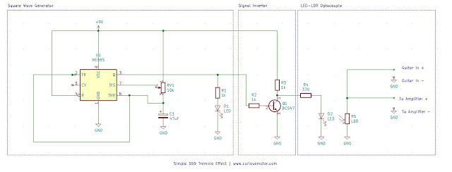
You can remove D1 once you’ve finished testing. The way in which circuit works is quite simple- The 555 produces a square wave in which the ON time is greater than the OFF time, this signal is inverted by an NPN transistor in the next section. And then finally, whenever the last LED(D2) glows, the LDR’s resistance decreases and almost shorts the signal creating a superb tremolo effect!

Simple Tremolo Effect using 555 and coupled LDR-LED ! from r/diypedals


Unknown
July 11, 2020 at 6:37 pmThis is dope! I have been messing around with this today, I added a 10K pot between the LED and the collector of the transistor (Currently using a 2n2222) And it seems to be working pretty decent as a depth control (By controlling the brightness of the led) Still looking into how to get rid of the 555 click (Very new to the 555 and electronics in general)
Siddharth Kothari
July 12, 2020 at 5:39 pmI'm glad it worked for you! A better way to add depth control is add a pot (use any two legs) between the LDR and ground!
.
January 1, 2021 at 5:42 amHey unknown, i kinda tried to investigate the clicknoise-problem in this circuit.
You wont get rid of it in this schematic until you have some light between D2 & R5.
As you can clearly see on the video, the LED to LDR is not covered, i.e no "Roach".
I would suggest to you and in generell a second yellow or warm white LED in the "Roach"- Housing, varied by an external Pot to control the .. mmhh.. Clickyness or Attack.
Know what i mean? 🙂
Unknown
December 20, 2020 at 10:01 pmHow to make it “choppier” so that the signal is completely interrupted (machine gun / helicopter effect)?
Thank You!