Introduction
A conventional guitar pedal is a device that tweaks/modifies the sound from an electric guitar by adding effects such as echo, delay, distortion, etc to the original signal. There are several ways in which this tweaking of sound can be achieved, one is using an analog circuit that amplifies and does something to the signal using discrete components. Another popular way these days, is by using the computer’s hardware to process sound with very complex effects by utilizing the computers inbuilt hardware. Several commercial products in this field such as NeuralDSP are gaining popularity.
CuriosPedal is a standalone pedal, that can be programmed using a computer, which in simpler words means, you can create your own effects with a bit of programming!
How does it work?
The main idea is quite straight forward-
1) The incoming guitar signal (a sinusoidal voltage) is converted to a digital signal using an ADC (Analog to Digital converter)
2) Then a processing unit plays around with the digital signal and modifies it to achieve a particular effect
3) A DAC (Digital to Analog converter) again converts the digital signal to analog so that it can be sent to the amplifier
4) and this goes on forever…
Typically the second part is done using mathematical algorithms (DSP) to uniformly modify the sound. There’s a superb collection of such algorithms here-
https://www.musicdsp.org/en/latest/
.
Implementation and Iterations
While I finished making the first prototype in a matter of hours, it took me several months to get rid of the ‘noise’ that was generated by the nature of the circuit and to some extent the code. Still, the circuit seems to be very noisy, probably due to grounding problems in the PCB.
The implementation bit
I chose the STM32F446 Nucleo board to be the processor for the pedal. In general, the STM32 boards are an excellent choice for a microcontroller as they are equipped with several peripherals and the STM32Cube IDE offers automatic code generation for basic settings!
I designed the pedal as a shield for this board, inspired by how convenient Arduino shields can be!
Here’s a schematic for the first prototype
(yes, its an OPEN- SOURCE project!)
Further,
here’s a link to the entire code on GitHub
. I’ll be writing the documentation once I’m done with the project and noise reduction bit.
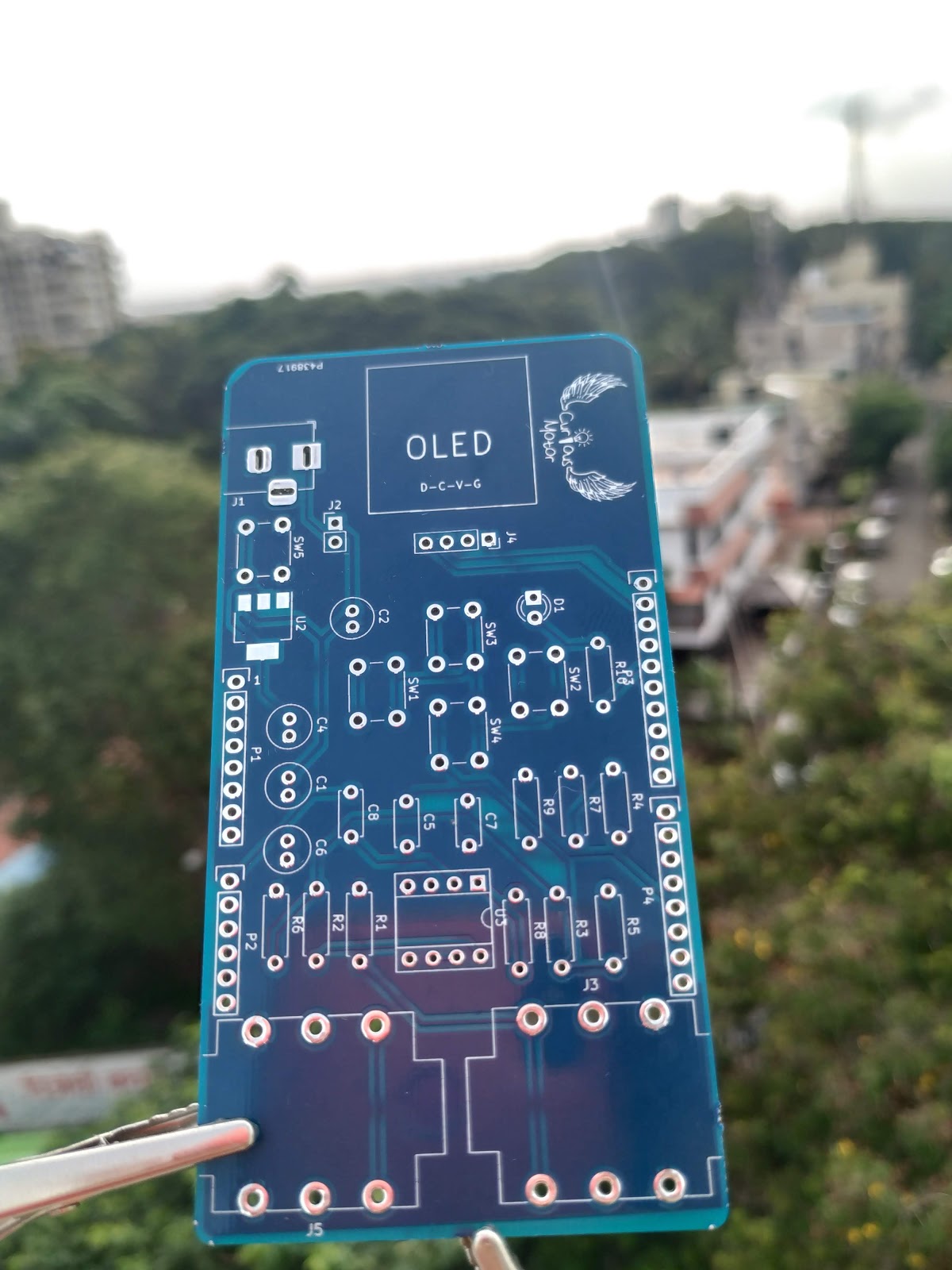
The most interesting part of the entire process for me was the PCB! I designed a PCB from scratch and got it fabricated from PCB Power, in Gujarat, India.
The progress gallery
 |
| 1.Breadboard prototype |
| 2. PCB designed using KiCAD |
| 3. 3D Rendering of the PCB |
 |
| 4. The real thing! |
 |
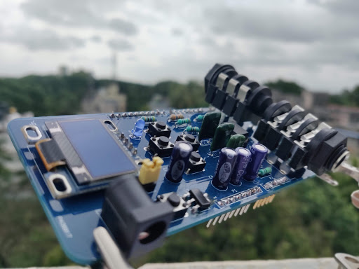
| 5. Components Soldered |
 |
| 6. All of it together! |
There’s a lot more that I want to share about this project, but as of now, it’s very hard to source components during the pandemic to further work on the project. It’s been very interesting to explore what all can be done at the intersection of music, maths, and electronics!
Stay creative,
Siddharth


Leave a Reply