

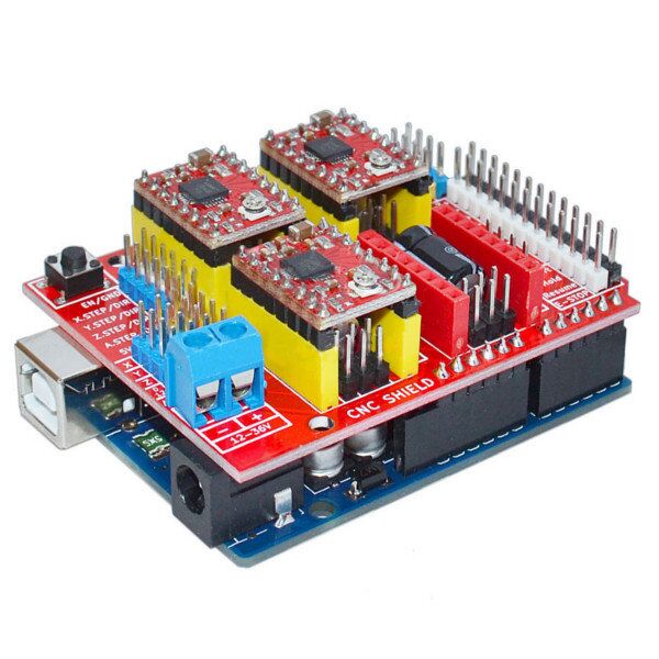
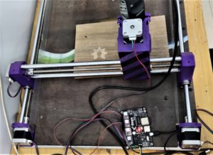
Sometime back, I built a CNC machine based on Nikodem Bartnik’s Dremel CNC. It was an easy build, however, I felt the electronics used in the project, were a bit obsolete. The Arduino UNO and CNC shield have been loyal to several generations of hobby CNC machines. But now, having a 32-bit board with WiFi isn’t badass, it’s the new normal.
After a quick brainstorming session, I and a classmate, Himanshu decided to design our very own stepper-motor-motherboard that would be WiFi-enabled and would use a powerful microcontroller. It wasn’t long before Google crushed the enterprising idea with examples of pioneering work already done in this field, far beyond what we planned. Nevertheless, we decided to make a completely open-source version as a tribute to the Open Source Community.
Absolutely everything about this project all the way from geeky simulations to rounded corners has been made possible by OS software, OS hardware, and lots of coffee.
Design Overview
All of the schematics and layout were designed on KiCAD, and the simulations were done on LTspice. All the open-source files of this project are available here – https://github.com/CuriousMotor/Onyx-Stepper-Motherboard
How’d we decide the components?
Well, we took two main factors into consideration. First, popularity, knowing that a particular component is used in several mass-produced designs, makes the design reliable. Second, availability on JLC Parts. Even before we designed the PCB, we decided to get the first prototype manufactured from JLC, so we made sure those components were available and well in stock there.
If you’re an electronics nerd, this next section of the blog is for you. Let’s take a brisk walk through the OnyxV1 design.
[Full Schematic can be viewed here]
Part One: Time to step down

We knew that we needed a circuit that would work with 12V as well as 24V, and convert that to 5V (2A) which would be further be regulated to 3.3V (via AMS1117) for the ESP32. That’s when I thought of looking at existing 3D printing motherboards to see how they’ve managed the power bit. The BigTreeTech SKR1.4 uses SGM6130, which seemed to be relatively hard to source in India. After a bit of Googling, I found TPS5430 which was the perfect DC-DC step-down converter for this project. The datasheet does a superb job of explaining the necessary calculations and it can be verified on the WEBENCH Simulator.
Part Two: USB-UART, Bridge over troubled water
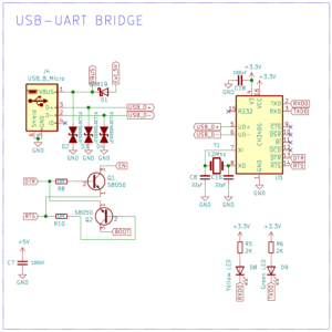
After a quick glance through how ESP32 dev boards incorporate a USB-UART bridge, we knew we had two options for choosing the chip- with CP2102 or CH340G. I was in complete favor of CP2102, since it didn’t require an external crystal and had far better documentation. While the CH340G, has its entire documentation in Chinese, it seemed to be well in stock and inexpensive to assemble at JLCPCB. And so we chose CH340G purely out of JLCPCB’s component stock at that time.
Part Three: A Microcontroller complete in itself
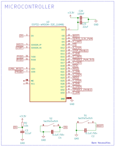
‘WiFi’ has been the main feature that we’ve been excited about. Having said that ESP32 has been our first and only choice. The one big mistake we did was opening the datasheet after completing a decent part of the design, only to find out ESP32-WROOM-32D is no longer recommended for new designs. Thankfully, we got to know ESP32-WROOM-32E was a drop-in replacement. We also considered using an STM32 with an 8266, but that would make the board far more complex, given that the ESP32 incorporates all the essential stuff in a compact module. This design was used as a reference for basic peripherals.
Part Four: One step at a time
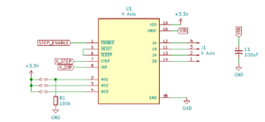
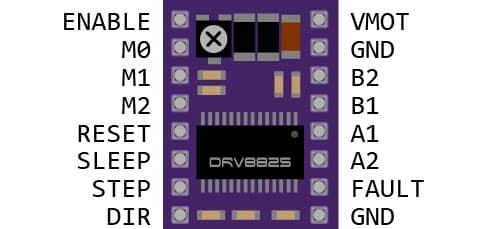
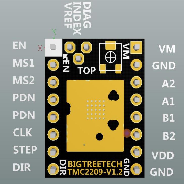
Okay, finally the confusing part- Stepper Motor Drivers. The moment we looked into the variety of stepper drivers and their pros and cons, we were overwhelmed by the options. The A4988 and DRV8825 are legacy drivers, but at the same time are inexpensive and the most popularly used ones. Advanced drivers like the TMC2209 and TMC2130 use UART/SPI for communication with the microcontroller and offer sensorless homing. However, all the four drivers mentioned above can work using the standard step/dir interface.
The main challenge was to design a footprint that could support all the drivers. Once again, the BigTreeTech SKR1.4 had already solved this problem, which made our work a bit easier. Their microcontroller LPC1769 had lots of GPIOs in excess and used jumpers for configuring the mode of operation. However, later we got to know that Barton Dring’s GRBL_ESP32 already has a way to run stepper drivers via the ESP32’s I2S peripheral using shift registers. The FYSTEC-E4 3D printer motherboard incorporates the same. Finally, we looked at our core objective, making a direct replacement for the CNC shield so we decided not to add UART/SPI jumpers, (and that’s something for version 2.0 🙂 ).
Part Five: Where were you while we were getting HIGH?
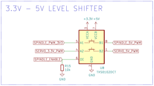
Servos and spindle controllers require 5V PWM for the control signal. Everything about the ESP32 on the other hand works on 3.3V. Now, there are a lot of CNC accessories that accept 5V for power and work with data signals at 3.3V. To be on the safer side, and not miss out on any HIGHs we used logic level translator TXS0102 which is a 2 channel, bi-directional logic level translator.
Part Six: The memorable part
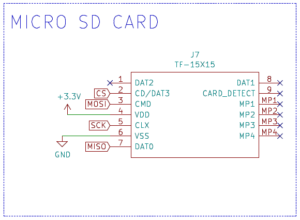
Now unless your laptop and CNC machine have a symbiotic relationship, it’s always better to save Gcode files in an SD card and have them to be executed without a laptop/computer sending data to it. SD cards work using SPI and are fairly easy to interface.
PCB Layout and Design
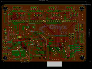
We referred to quite a few CNC/3D printer motherboards, especially the FYSTEC-E4 and BTT SKR1.4, for understanding PCB ergonomics. What made it considerably challenging was making optimal use of a 2-layer board, as compared to all popular CNC motherboards that were 4-layer PCBs. The main idea behind using a 2-layer board was to keep the manufacturing costs low. I wrote a Reddit post asking for advice- 2 layers vs 4 layers and got mixed replies. Long story short – We designed it on 2 layers with proper grounding (front and back GND pours stitched with vias) and it worked like a charm.
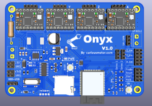
Here’s a super cool in-browser viewable 3D model of the board!
Conclusion
All in all its been a very rewarding experience to design an open-source CNC motherboard. There were a few assembly mistakes that we had to correct by resoldering a few diodes, that are now fixed in the GitHub repo. We tested the board with my Dremel CNC and it worked like a charm. As a bonus, there are GRBL apps on the PlayStore that allows one to control the machine via Bluetooth using any android phone!
If you’ve read this far, do leave a comment and let me know your take on this project! Show your support for this project by ‘Star-ing⭐’ the project repo – https://github.com/CuriousMotor/Onyx-Stepper-Motherboard
Cheers!


GANESH KUMAR RAI
December 29, 2021 at 4:43 amWow, Siddharth & Himanshu, very interesting. It’s really good to see such innovative ideas.
Aron Ayub
December 29, 2021 at 1:52 pmHave taken my time to check this project , it’s perfect and interesting one.
Good gesture here. A lot of time spent on it but still gives it freely. Something to emulate, especially them that still don’t give their content freely in the community.
Bui
August 29, 2022 at 10:58 amOnyx V1.0 can the 12864 LCD screen be extended?
Siddharth
September 8, 2022 at 6:38 amUnfortunately, not yet 🙂
Bui
November 23, 2022 at 3:22 pmlàm ơn hãy cho tôi biết khi nào Onyx V1.0 có thể kết nối được với màn hình điều khiển và thẻ nhớ hoặc ổ đĩa USB, Xin cảm ơn!