If you have worked with guitar pedals and audio circuits in general, you may already know how capacitors are used as low/high pass filters. While designing non-distortion guitar pedals (tremolo, reverb, delay, etc.), a designer uses capacitors in some way or the other to make sure that all the amplification and equalization does not bring in any sort of distortion.
The question is how do you filter out distortion?
This article is about one of the most exciting concepts that exploit the beauty of science and math to provide an altogether new way of thinking about circuits.
Before we arrive at the ‘aha-moment’, here’s a little electronics primer so that we’re on the same page.
If you are already good with low pass filters you can skip reading till you see a bold blue text that says ‘skip till here’.
What you see below is called a low pass filter circuit (or to be more precise a passive low pass filter circuit).
Such a filter circuit allows low-frequency signals to pass easily and diminish the higher frequency signals. In other words, all the squeaky sounds will be diminished and the lower-pitched sounds would remain unaltered. For completeness, let’s also quickly discuss how this circuit works.
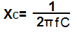
The impedance (capacitive reactance) of a capacitor is given by-
where f= frequency of the input signal (Hertz or Hz)
and C= The capacitance of the capacitor (Farads or F)
It’s easy to see from the formula if the frequency or the capacitance increases, the capacitor’s impedance decreases. Naturally, the capacitance of the capacitor is not something that can change, so what matters is the frequency. The moment the circuit is fed with a high-frequency signal, the capacitor, with its impedance reduced, happily welcomes the signal to ground, hence reducing the output signal. Notice the circuit is basically, nothing more than a
voltage-divider
circuit.
–SKIP TILL HERE–
A lot of guitar pedals I’ve come across, use such passive low pass filters to apparently cut off noise from signals.
For instance, in the
previous post
, we came across a filtering capacitor.
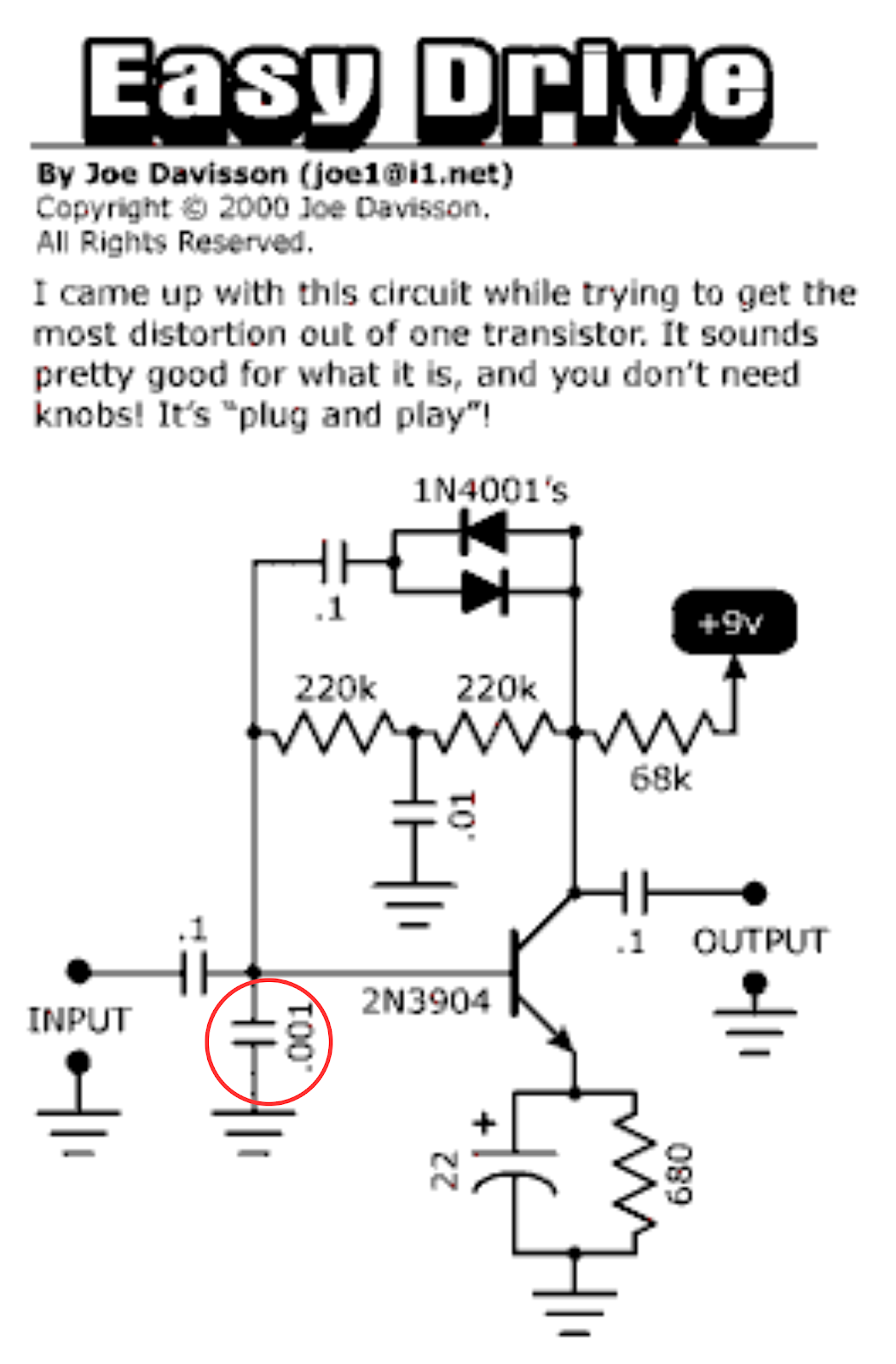 |
| The filter capacitor is circled in red. |
The first thing you should notice is that the capacitor’s value is very small, in fact, its smallest capacitor value in this circuit. Had it been a bigger value, it would drastically reduce the signal’s volume by filtering out lower frequencies as well. If you Google, you can find such capacitors in almost any guitar pedal.
Now, what question exactly are we trying to address?
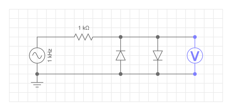
Have a look at this circuit-
This is the simplest clipping circuit possible. Let’s also have a look at what the output voltmeter reads.
 |
| Click to enlarge |
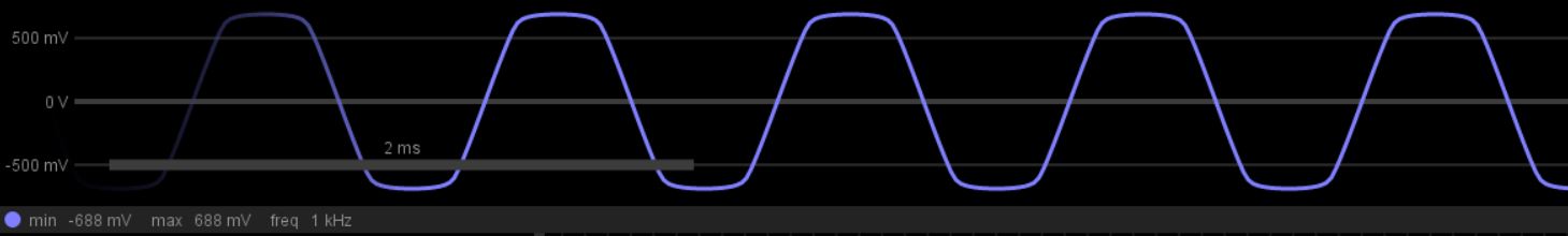
As expected, the output is clipped at almost 0.7 Volts.
Let’s say this is the output of a fuzz/distortion pedal. Now, for some reason, we decide to add a capacitor between the output and ground, so that our circuit would look like this-
Have a look at the output as well-
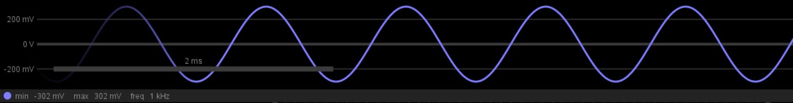 |
| Click to enlarge |
At this point, you really should be surprised, because what we’ve just managed to do, is obtain the original un-distorted clean signal (as if the signal never went through a fuzz/distortion pedal), although the volume would be drastically lower than the distorted signal. But, that’s what opamps are for!
There are several ways to explain why this happens, one way is to understand how the currents and voltages are behaving in the circuit, and another one is through a beautiful concept from math. I believe the second way is more rewarding in a number of ways and is a much more versatile method.
Let’s finally get to what we’re here for!
Your intuition should tell you that the key difference between the two circuits above is that the second circuit has a LOW PASS FILTER. In some way, by apparently filtering out higher frequencies, we managed to get back the original signal.
But there’s only one signal here that we’re dealing with. This could potentially mean that ‘the one signal’ we are dealing with has two or more parts/components-
1. A high-frequency component
2. A low-frequency component
You should already have a hint of what this is leading to. Having said all this, let’s go through a slightly more formal proof that would elaborate on the idea of multiple components in a single signal.
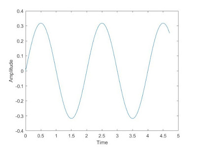
Below, is a sine curve with some frequency, just like the input signal of a guitar. Henceforth, I’ll be referring to this signal as the original signal.
And now here’s the same signal with 3 times the frequency and 1/3rd of the amplitude.
By adding both of them we get a signal that’s no longer a sine signal but still has the same frequency as the original signal.
This should be the ‘aha-moment’ for you and if it isn’t, no worries, hold tight, the next few steps should give you a clearer view of where this discussion is leading to.
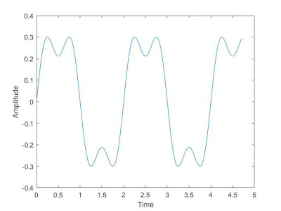
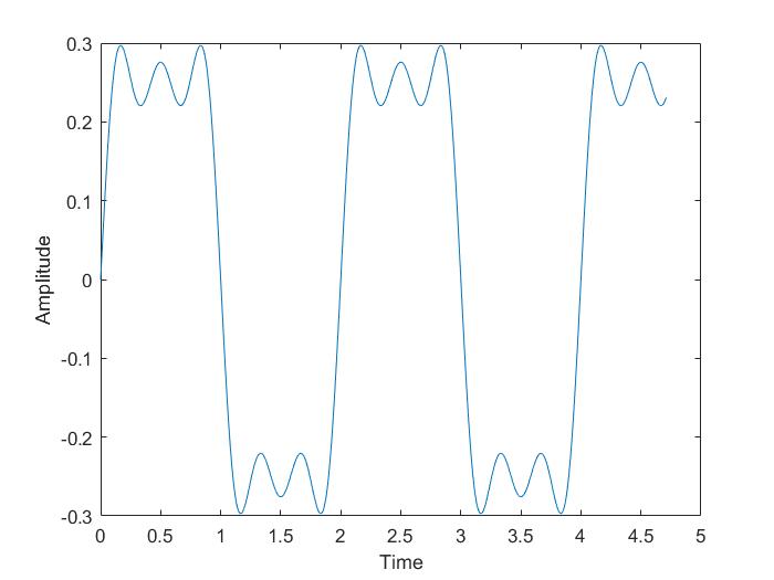
By adding one more signal that’s 5 times the original frequency but has 1/5th of the original amplitude to the above-combined signal, we get-
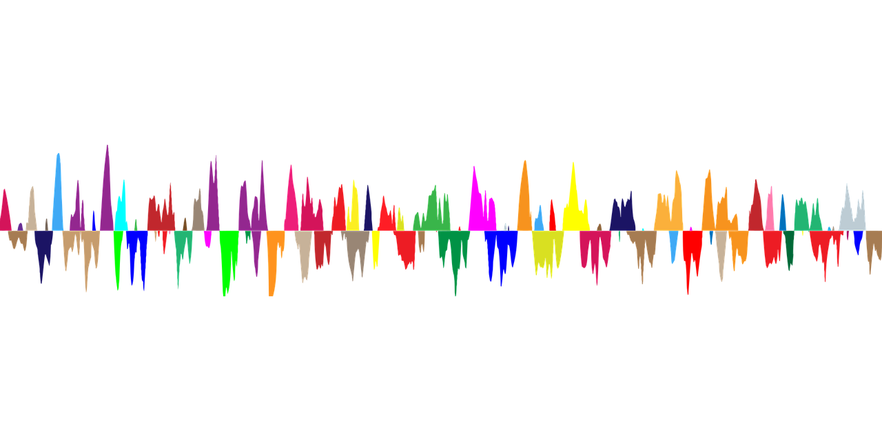
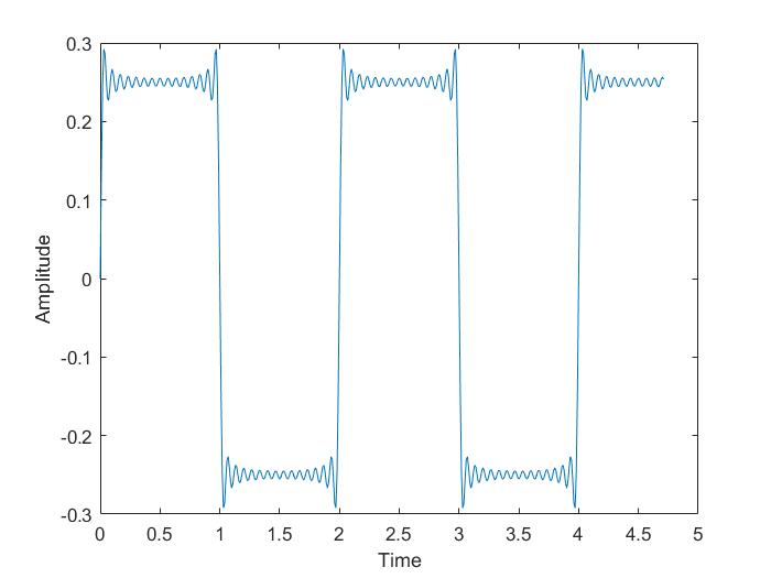
And by adding a few more signals that are x times the original frequency and have 1/xth of the original amplitude, here’s what the plot looks like!
This kind of squarishness resembles the output of a fuzz/distortion pedal.
What’s interesting is that we’ve landed up with this squarish distorted signal by simply adding scaled sine signals of higher frequencies!
Connecting the dots
This should be enough proof to understand that the distorted signal is nothing but a bunch of higher frequency sine waves added to the original signal. If you remove all the high-frequency components, what do you get back??
And hence the entire low-pass-filter story…
This wonderfully elegant concept we’ve discussed all the way is called the Fourier series. And t
his is a gripping video
that exploits this concept to make entire drawings using just sine waves(Fourier series!).
As a bonus, any signal can be decomposed into its constituent sine waves by a little mathematics known as the Fourier transform.
All feedback is highly appreciated, whether positive or negative 🙂
Cheers,
Siddharth


Leave a Reply